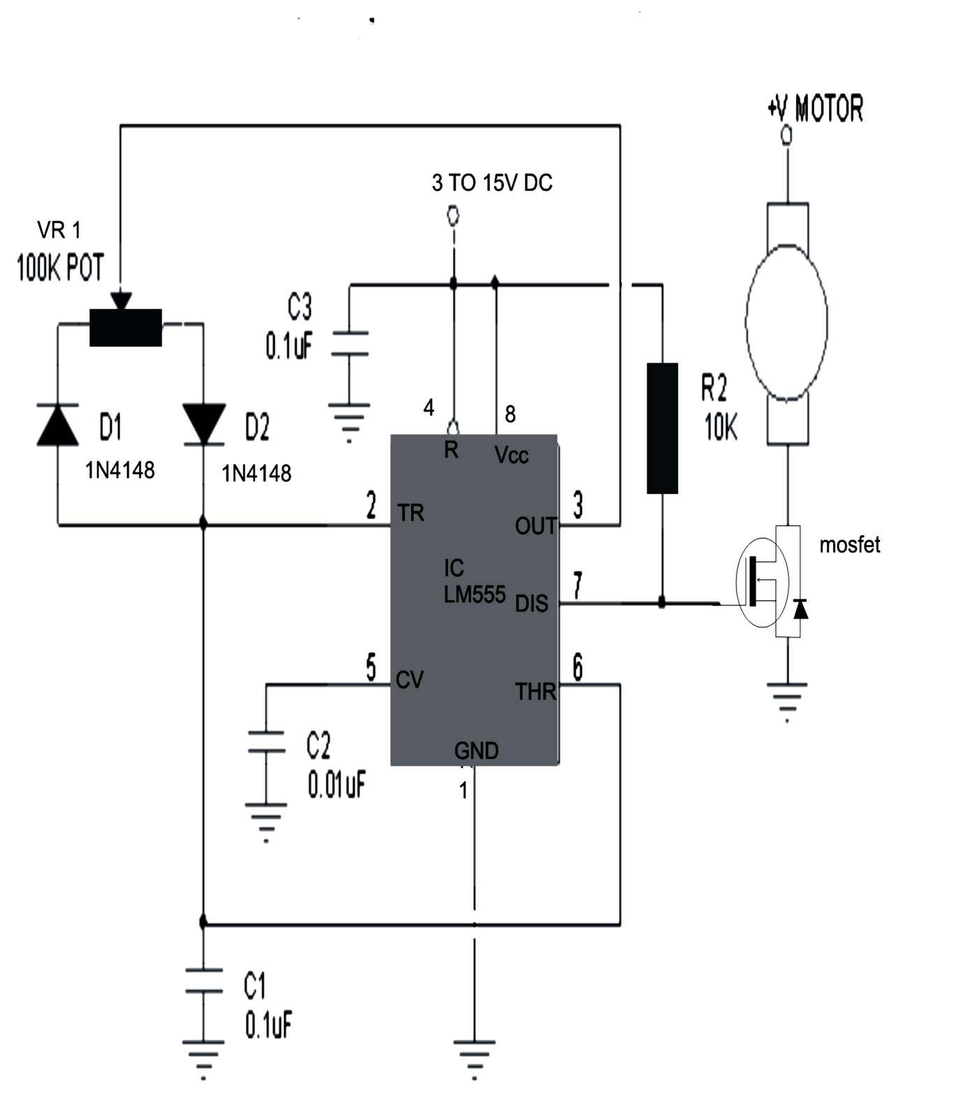
Pwm Power Supply Circuit Diagram Pwm Circuit Diagram
Pwm inverter circuit 3200v power supply circuit diagram High voltage power supply based pwm ic tl494
pwm circuit diagram using 555 - IOT Wiring Diagram
Pwm power supply circuit diagram A simple 555 pwm circuit with motor example Pulse width modulation (pwm) circuit
0-30v variable power supply circuit diagram at 3a
How to design the pwm circuitryMotor circuit speed controller ne555 pwm dc pcb layout diagram based electronic simple ic visit Motor circuit dc speed pwm controller control circuits simple brushed diagram make 555 ic based 24vdc schematic potentiometer current helpPwm circuit diagram.
Pwm power supply schematicPwm technique in inverter Pwm circuit diagram using 555Adjustable or variable power supply circuit diagram (0-30v) in 2023.

Power controller circuit diagram
Pwm power supply circuit diagramCircuit mppt solar pwm charger panel simple battery 555 ic power circuits using homemade optimizer converter based voltage panels energy Pwm circuit mosfet analog control switching load pcb example filter high led frequency simple signal circuitry ripple brightness lightFalming: [1+] cpu wiring diagram 4 pin relay, how to hook up a 5 pin relay.
Supply variable 30v eleccircuit voltage constant psu flowPwm power supply circuit diagram Supply power voltage high scheme tl494 circuit pwm ic schematic diagram based circuits 12vDc motor speed control pwm circuit.

5 simple dc motor speed controller circuits explained – homemade
How to make a solar panel optimizer circuit – homemade circuit projectsPwm power supply circuit diagram Pwm power supply circuit diagramNe555 based pwm dc motor speed controller circuit with pcb layout.
.


![falming: [1+] Cpu Wiring Diagram 4 Pin Relay, How To Hook Up A 5 Pin Relay](https://i2.wp.com/forum.duet3d.com/assets/uploads/files/1550853816555-fans.jpg)
