Process Flow Diagram Igcc Plant Igcc Energy Flow Diagram Pro
Basic flow sheet of an igcc plant Process flowsheet of the igcc plant integrating a psa and co2 Simplified diagram for the igcc process [ix]
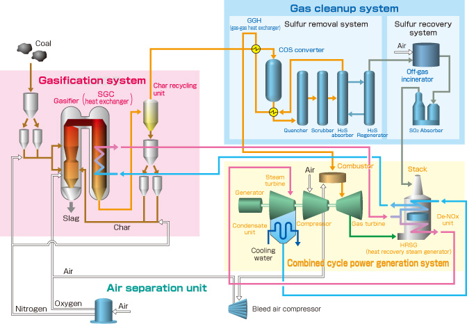
Typical Integrated Gasification Combined Cycle (IGCC) Configuration
Clc asu igcc integration sections represents configuration respectively gasification Igcc gasification coal netl doe typical Typical integrated gasification combined cycle (igcc) configuration
Igcc integrated gasification
Flow diagram of igcc+ccs processPower igcc turbine gas flow steam efficiency coal polk units integrated simplified mulberry gasification electricity biomass coke integrate duo Flow diagram of the igcc processSchematic igcc flowsheet psa.
Schematic of igcc flowsheet with et psa processProcess flow diagram of igcc power plant without ccs system Igcc otm integrated captureProcess flow diagram for rfg-based igcc-cc.

Flow diagram of igcc with co2 capture
Process flow diagram of the igccFlow diagram of a conventional igcc plant with co 2 capture Igcc reactor clc bglPlant igcc energy flow diagram process sustainable future.
Integrated gasification combined cycle igccBlock flow diagram of the igcc with pre-combustion co2 capture Igcc-integrated gasification combined cycle กับถ่านหินเกรดต่ำ ตอนที่ 4/Igcc cycle combined gasification integrated warming global diagram coal greenhouse advantages energy.
![Simplified diagram for the IGCC process [ix] | Download Scientific Diagram](https://i2.wp.com/www.researchgate.net/profile/Isah_Mohammed4/publication/291411920/figure/download/fig1/AS:667841539874821@1536237239302/Simplified-diagram-for-the-IGCC-process-ix.ppm)
Capture combustion flow igcc
Flow diagram of igcc+ccs processSchematic of igcc flowsheet with selexol process Igcc capturePlant power gas igcc diagram cycle gasification coal combined natural integrated clean process per.
Advanced flow sheet diagram of an igcc power plant [6].Diagram flow process igcc plant gasification power coal syngas cycle combined diagrams integrated doe tampa electric cleanup steam typical water Team:ncku tainan/applied designIgcc advanced.

Energy for sustainable future: nakoso igcc plant
Igcc update: are we there yet?Ccs igcc Diagram igcc flow power process energy single plant coal charts line gasification cycle simple integrated thefraserdomain typepad visitThe largest clean coal power plant in america turns to natural gas.
Igcc plant ccs schematicProcess flow diagram of the igcc Mhi wins contract to perform feed for igcc project in californiaSchematic of igcc plant with ccs [9].

Process flow diagram for igcc-clc process with air-cooling and asu
Typical integrated gasification combined cycle (igcc) configuration2: process flow diagram of an igcc power station integrating a co 2 Igcc tainan ncku igem vattenfall flow fig process diagram source 2010Process block diagram for otm integrated igcc plant with co 2 capture.
Igcc conventionalSimplified igcc ix Advanced flow sheet diagram of an igcc power plant [6].Typical integrated gasification combined cycle (igcc) configuration.

Igfc (igcc)
The energy blog: about igcc power plants11: flow diagram of the igcc plant using a two-reactor clc unit and a 1: schematic of an integrated gasification combined cycle (igccIgcc flowsheet schematic psa fig elevated techno swing co2.
.


![Schematic of IGCC Plant with CCS [9] | Download Scientific Diagram](https://i2.wp.com/www.researchgate.net/publication/318656667/figure/fig1/AS:519647206543360@1500904956473/Schematic-of-IGCC-Plant-with-CCS-9.png)
